The forum is currently inactive due to too much AI spam.
EVC2 VMOD1-header Tutorial
Quote from elmor on 2019-08-06, 15:36The EVC2 can digitally perform FB (feedback) modification on analog VRM controllers. This works by using an on-board current-DAC which sources or sinks current into the FB pin. The current-DAC is a Maxim DS4404+ (on EVC2N4) and the datasheet has good information on theory of operation: https://datasheets.maximintegrated.com/en/ds/DS4402-DS4404.pdf. EVC2S uses a custom DAC circuit which can only sink current. EVC2SX uses a NCT3933U current-DAC: https://static6.arrow.com/aropdfconversion/6ed8f44d277d4e653c6df4ec484b30ddb9ab05e7/nct3933u_datasheet_a2.pdf
- SRCx pins are connected to the current-DAC for sourcing or sinking current from the VRM controller FB pin.
- VINx is for output voltage monitoring. Step-size = 1.6mV, max input 6.6V, tolerant up to 8.0V.
EVC2N4
- SRC1 step-size is 2.1 μA, range up to +/- 2000 μA
- SRC2 step-size is 16.1 μA, ranges up to +/- 500 μA
EVC2S
- SRC1 step-size varies (max 0.6μA), range to -920 µA
EVC2SX
- SRC1 step-size 10 µA, +/- 1270µA
- SRC2 step-size 10 µA, +/- 1270µA
- SRC3 step-size 10 µA, +/- 1270µA
Theory of operation
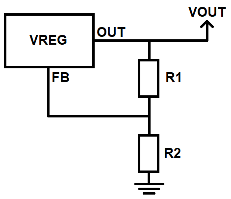
A typical analog VRM controller has a feedback loop with optional compensation network which adjusts the output set-point. Simplified it looks like this:
Normally the output voltage is decided by the equation Vout = Vref*(R1/R2 + 1), where Vref is the voltage at the FB pin. This equation and Vref value should be noted in the VRM controller datasheet. Sinking or sourcing current from the FB pin will offset the output by R1*Idac (decrease from sourcing and increase from sinking).
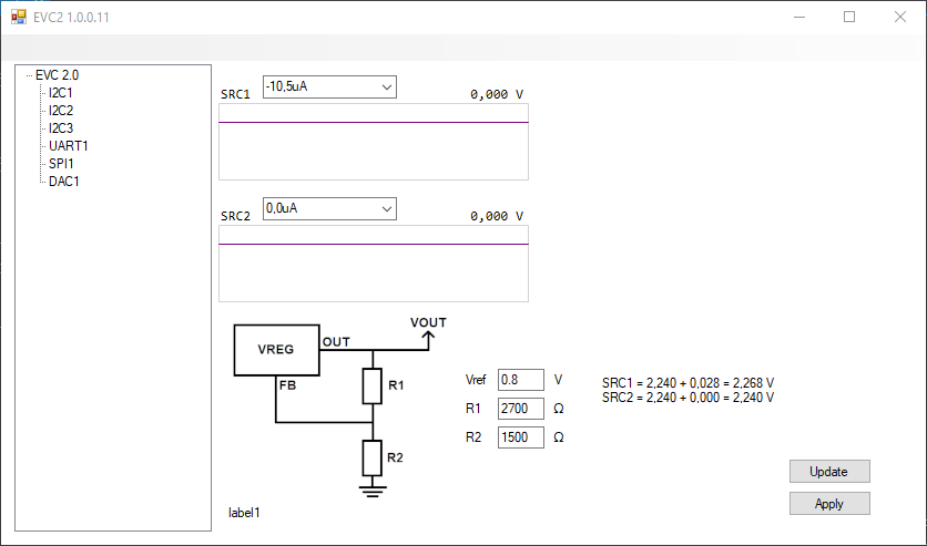
For example the EVC2 on-board LDO (low-dropout regulator) AP7167 (U5 SOP-8L-EP) (https://www.diodes.com/assets/Datasheets/AP7167.pdf) lists this equation and Vref=0.8V. On EVC2 R1 = 2.7kΩ and R2 = 1.5kΩ. You can try yourself using this LDO by soldering SRCx to U5 FB (pin#6) and VINx to U5 OUT (pin#7 or 8). The LDO first needs to be enabled under SPI1 and the output voltage should be set to 2.235V to not have any offset.
Vout = 0.8*(2700/1500+1) = 2.24V
If we sink 10μA (negative) from the FB pin:
Offset = R1*Idac = 2700*10e-6 = 0.027V
Vout+Offset = 2.24V + 0.027V = 2.267V
Practical step by step
- Measure resistance R1 from FB to Vout
- Measure resistance R2 from FB to GND
- Measure Vref voltage at the FB pin
- Connect SRCx to FB
- Connect VINx to Vout
- Enter parameters in the EVC2 software which will help you calculate the resulting voltage
- First test with sourcing current (positive values) which will decrease the voltage in case the steps are too large
The EVC2 can digitally perform FB (feedback) modification on analog VRM controllers. This works by using an on-board current-DAC which sources or sinks current into the FB pin. The current-DAC is a Maxim DS4404+ (on EVC2N4) and the datasheet has good information on theory of operation: https://datasheets.maximintegrated.com/en/ds/DS4402-DS4404.pdf. EVC2S uses a custom DAC circuit which can only sink current. EVC2SX uses a NCT3933U current-DAC: https://static6.arrow.com/aropdfconversion/6ed8f44d277d4e653c6df4ec484b30ddb9ab05e7/nct3933u_datasheet_a2.pdf
- SRCx pins are connected to the current-DAC for sourcing or sinking current from the VRM controller FB pin.
- VINx is for output voltage monitoring. Step-size = 1.6mV, max input 6.6V, tolerant up to 8.0V.
EVC2N4
- SRC1 step-size is 2.1 μA, range up to +/- 2000 μA
- SRC2 step-size is 16.1 μA, ranges up to +/- 500 μA
EVC2S
- SRC1 step-size varies (max 0.6μA), range to -920 µA
EVC2SX
- SRC1 step-size 10 µA, +/- 1270µA
- SRC2 step-size 10 µA, +/- 1270µA
- SRC3 step-size 10 µA, +/- 1270µA
Theory of operation
A typical analog VRM controller has a feedback loop with optional compensation network which adjusts the output set-point. Simplified it looks like this:
Normally the output voltage is decided by the equation Vout = Vref*(R1/R2 + 1), where Vref is the voltage at the FB pin. This equation and Vref value should be noted in the VRM controller datasheet. Sinking or sourcing current from the FB pin will offset the output by R1*Idac (decrease from sourcing and increase from sinking).
For example the EVC2 on-board LDO (low-dropout regulator) AP7167 (U5 SOP-8L-EP) (https://www.diodes.com/assets/Datasheets/AP7167.pdf) lists this equation and Vref=0.8V. On EVC2 R1 = 2.7kΩ and R2 = 1.5kΩ. You can try yourself using this LDO by soldering SRCx to U5 FB (pin#6) and VINx to U5 OUT (pin#7 or 8). The LDO first needs to be enabled under SPI1 and the output voltage should be set to 2.235V to not have any offset.
Vout = 0.8*(2700/1500+1) = 2.24V
If we sink 10μA (negative) from the FB pin:
Offset = R1*Idac = 2700*10e-6 = 0.027V
Vout+Offset = 2.24V + 0.027V = 2.267V
Practical step by step
- Measure resistance R1 from FB to Vout
- Measure resistance R2 from FB to GND
- Measure Vref voltage at the FB pin
- Connect SRCx to FB
- Connect VINx to Vout
- Enter parameters in the EVC2 software which will help you calculate the resulting voltage
- First test with sourcing current (positive values) which will decrease the voltage in case the steps are too large
Quote from elmor on 2020-04-23, 23:31Quote from Aaron on 2020-04-23, 22:48Quote from elmor on 2020-04-23, 13:45Quote from Aaron on 2020-04-23, 06:48Hello,
I am one of the newbies that got the EVC2 after der8auer used and mentioned it in his last video. From what I can read in the description and what der8auer mentioned in his video, it can also be used on analog voltage controllers. I mainly got it to gain control over my GTX1080 which uses an uP9511 for some DICE/LN2. Is this chip supported and if yes how would I set it up ?
Apart from that thank you for building such a nice tool.
Hello, yes it's possible. Check out this topic: https://www.elmorlabs.com/index.php/forum/topic/evc2-vmod1-header-tutorial/
Let me know if anything isn't clear 🙂
Fisrt of all thank you for the fast reply 🙂 I understand most of it, however the Vout formula from the uP9511 doesnt look like this "Vout = Vref*(R1/R2 + 1)" at all. Im not sure if it still works then and what I might have to do different. Here is a link to the datasheet, I will also add a little picture with the formula.
https://www.icware.ru/pdf/0004239.pdf
On uP9511 I'd suggest you modify the REFIN voltage instead of through the FB circuit. The input voltage to this pin is mimicked at the output.
If you don't consider the added voltage from the REFADJ output (PWMVID controlled), it's a simple voltage divider.
Vref = 2.0V
Rtop = R2+R3
Rbot = R4+R5
Vout = 2.0V*Rbot/(Rtop+Rbot)
If you add the DAC current adjustment at the REFIN point, I get the following:
Vout = Rbot*(2.0V - Rtop*Idac)/(Rtop+Rbot)
edit: Fixed the last formula where I assumed Rtop = R1 and Rbot = R2
Quote from Aaron on 2020-04-23, 22:48Quote from elmor on 2020-04-23, 13:45Quote from Aaron on 2020-04-23, 06:48Hello,
I am one of the newbies that got the EVC2 after der8auer used and mentioned it in his last video. From what I can read in the description and what der8auer mentioned in his video, it can also be used on analog voltage controllers. I mainly got it to gain control over my GTX1080 which uses an uP9511 for some DICE/LN2. Is this chip supported and if yes how would I set it up ?
Apart from that thank you for building such a nice tool.
Hello, yes it's possible. Check out this topic: https://www.elmorlabs.com/index.php/forum/topic/evc2-vmod1-header-tutorial/
Let me know if anything isn't clear 🙂
Fisrt of all thank you for the fast reply 🙂 I understand most of it, however the Vout formula from the uP9511 doesnt look like this "Vout = Vref*(R1/R2 + 1)" at all. Im not sure if it still works then and what I might have to do different. Here is a link to the datasheet, I will also add a little picture with the formula.
On uP9511 I'd suggest you modify the REFIN voltage instead of through the FB circuit. The input voltage to this pin is mimicked at the output.
If you don't consider the added voltage from the REFADJ output (PWMVID controlled), it's a simple voltage divider.
Vref = 2.0V
Rtop = R2+R3
Rbot = R4+R5
Vout = 2.0V*Rbot/(Rtop+Rbot)
If you add the DAC current adjustment at the REFIN point, I get the following:
Vout = Rbot*(2.0V - Rtop*Idac)/(Rtop+Rbot)
edit: Fixed the last formula where I assumed Rtop = R1 and Rbot = R2
Uploaded files: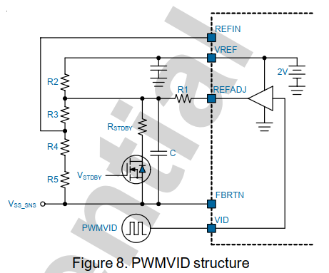
Quote from Minium on 2020-04-24, 00:23Quote from elmor on 2020-04-23, 23:31Quote from Aaron on 2020-04-23, 22:48Quote from elmor on 2020-04-23, 13:45Quote from Aaron on 2020-04-23, 06:48Hello,
I am one of the newbies that got the EVC2 after der8auer used and mentioned it in his last video. From what I can read in the description and what der8auer mentioned in his video, it can also be used on analog voltage controllers. I mainly got it to gain control over my GTX1080 which uses an uP9511 for some DICE/LN2. Is this chip supported and if yes how would I set it up ?
Apart from that thank you for building such a nice tool.
Hello, yes it's possible. Check out this topic: https://www.elmorlabs.com/index.php/forum/topic/evc2-vmod1-header-tutorial/
Let me know if anything isn't clear 🙂
Fisrt of all thank you for the fast reply 🙂 I understand most of it, however the Vout formula from the uP9511 doesnt look like this "Vout = Vref*(R1/R2 + 1)" at all. Im not sure if it still works then and what I might have to do different. Here is a link to the datasheet, I will also add a little picture with the formula.
https://www.icware.ru/pdf/0004239.pdf
On uP9511 I'd suggest you modify the REFIN voltage instead of through the FB circuit. The input voltage to this pin is mimicked at the output.
If you don't consider the added voltage from the REFADJ output (PWMVID controlled), it's a simple voltage divider.
Vref = 2.0V
Rtop = R2+R3
Rbot = R4+R5
Vout = 2.0V*Rbot/(Rtop+Rbot)
If you add the DAC current adjustment at the REFIN point, I get the following:
Vout = Rbot*(2.0V - R1*Idac)/(R1+R2)
Thank you. As im no expert at reading these diagrams I will stuggle to measure the various resistances I need to calculate output voltage.
For example to get R2+R3 I would measure between VREF and REFIN. For R4+R5 between REFIN and FBRTN. To get R1+R2 I would measure between VREF and REFADJ. To get R1 I have no idea what to do.
I'm sure these measurements are easy to do but I just dont have experience with it at all and I get confused because I dont knwo how to read the diagram correctly.
To add DAC adjustment at REFIN I assume I connect SRCx to REFIN and VINx to some point where I can measure GPU voltage. Im not sure if this even makes sense but im trying to undersatnd all this.
I hope I dont take up time you could use way better with these noob questions.
Quote from elmor on 2020-04-23, 23:31Quote from Aaron on 2020-04-23, 22:48Quote from elmor on 2020-04-23, 13:45Quote from Aaron on 2020-04-23, 06:48Hello,
I am one of the newbies that got the EVC2 after der8auer used and mentioned it in his last video. From what I can read in the description and what der8auer mentioned in his video, it can also be used on analog voltage controllers. I mainly got it to gain control over my GTX1080 which uses an uP9511 for some DICE/LN2. Is this chip supported and if yes how would I set it up ?
Apart from that thank you for building such a nice tool.
Hello, yes it's possible. Check out this topic: https://www.elmorlabs.com/index.php/forum/topic/evc2-vmod1-header-tutorial/
Let me know if anything isn't clear 🙂
Fisrt of all thank you for the fast reply 🙂 I understand most of it, however the Vout formula from the uP9511 doesnt look like this "Vout = Vref*(R1/R2 + 1)" at all. Im not sure if it still works then and what I might have to do different. Here is a link to the datasheet, I will also add a little picture with the formula.
On uP9511 I'd suggest you modify the REFIN voltage instead of through the FB circuit. The input voltage to this pin is mimicked at the output.
If you don't consider the added voltage from the REFADJ output (PWMVID controlled), it's a simple voltage divider.
Vref = 2.0V
Rtop = R2+R3
Rbot = R4+R5
Vout = 2.0V*Rbot/(Rtop+Rbot)
If you add the DAC current adjustment at the REFIN point, I get the following:
Vout = Rbot*(2.0V - R1*Idac)/(R1+R2)
Thank you. As im no expert at reading these diagrams I will stuggle to measure the various resistances I need to calculate output voltage.
For example to get R2+R3 I would measure between VREF and REFIN. For R4+R5 between REFIN and FBRTN. To get R1+R2 I would measure between VREF and REFADJ. To get R1 I have no idea what to do.
I'm sure these measurements are easy to do but I just dont have experience with it at all and I get confused because I dont knwo how to read the diagram correctly.
To add DAC adjustment at REFIN I assume I connect SRCx to REFIN and VINx to some point where I can measure GPU voltage. Im not sure if this even makes sense but im trying to undersatnd all this.
I hope I dont take up time you could use way better with these noob questions.
Quote from elmor on 2020-04-24, 01:56Quote from Aaron on 2020-04-24, 00:23Quote from elmor on 2020-04-23, 23:31Quote from Aaron on 2020-04-23, 22:48Quote from elmor on 2020-04-23, 13:45Quote from Aaron on 2020-04-23, 06:48Hello,
I am one of the newbies that got the EVC2 after der8auer used and mentioned it in his last video. From what I can read in the description and what der8auer mentioned in his video, it can also be used on analog voltage controllers. I mainly got it to gain control over my GTX1080 which uses an uP9511 for some DICE/LN2. Is this chip supported and if yes how would I set it up ?
Apart from that thank you for building such a nice tool.
Hello, yes it's possible. Check out this topic: https://www.elmorlabs.com/index.php/forum/topic/evc2-vmod1-header-tutorial/
Let me know if anything isn't clear 🙂
Fisrt of all thank you for the fast reply 🙂 I understand most of it, however the Vout formula from the uP9511 doesnt look like this "Vout = Vref*(R1/R2 + 1)" at all. Im not sure if it still works then and what I might have to do different. Here is a link to the datasheet, I will also add a little picture with the formula.
https://www.icware.ru/pdf/0004239.pdf
On uP9511 I'd suggest you modify the REFIN voltage instead of through the FB circuit. The input voltage to this pin is mimicked at the output.
If you don't consider the added voltage from the REFADJ output (PWMVID controlled), it's a simple voltage divider.
Vref = 2.0V
Rtop = R2+R3
Rbot = R4+R5
Vout = 2.0V*Rbot/(Rtop+Rbot)
If you add the DAC current adjustment at the REFIN point, I get the following:
Vout = Rbot*(2.0V - R1*Idac)/(R1+R2)
Thank you. As im no expert at reading these diagrams I will stuggle to measure the various resistances I need to calculate output voltage.
For example to get R2+R3 I would measure between VREF and REFIN. For R4+R5 between REFIN and FBRTN. To get R1+R2 I would measure between VREF and REFADJ. To get R1 I have no idea what to do.
I'm sure these measurements are easy to do but I just dont have experience with it at all and I get confused because I dont knwo how to read the diagram correctly.
To add DAC adjustment at REFIN I assume I connect SRCx to REFIN and VINx to some point where I can measure GPU voltage. Im not sure if this even makes sense but im trying to undersatnd all this.
I hope I dont take up time you could use way better with these noob questions.
I'm sorry, my mistake. It's supposed to be:
Vout = Rbot*(2.0V - Rtop*Idac)/(Rtop+Rbot)
Quote from Aaron on 2020-04-24, 00:23Quote from elmor on 2020-04-23, 23:31Quote from Aaron on 2020-04-23, 22:48Quote from elmor on 2020-04-23, 13:45Quote from Aaron on 2020-04-23, 06:48Hello,
I am one of the newbies that got the EVC2 after der8auer used and mentioned it in his last video. From what I can read in the description and what der8auer mentioned in his video, it can also be used on analog voltage controllers. I mainly got it to gain control over my GTX1080 which uses an uP9511 for some DICE/LN2. Is this chip supported and if yes how would I set it up ?
Apart from that thank you for building such a nice tool.
Hello, yes it's possible. Check out this topic: https://www.elmorlabs.com/index.php/forum/topic/evc2-vmod1-header-tutorial/
Let me know if anything isn't clear 🙂
Fisrt of all thank you for the fast reply 🙂 I understand most of it, however the Vout formula from the uP9511 doesnt look like this "Vout = Vref*(R1/R2 + 1)" at all. Im not sure if it still works then and what I might have to do different. Here is a link to the datasheet, I will also add a little picture with the formula.
On uP9511 I'd suggest you modify the REFIN voltage instead of through the FB circuit. The input voltage to this pin is mimicked at the output.
If you don't consider the added voltage from the REFADJ output (PWMVID controlled), it's a simple voltage divider.
Vref = 2.0V
Rtop = R2+R3
Rbot = R4+R5
Vout = 2.0V*Rbot/(Rtop+Rbot)
If you add the DAC current adjustment at the REFIN point, I get the following:
Vout = Rbot*(2.0V - R1*Idac)/(R1+R2)
Thank you. As im no expert at reading these diagrams I will stuggle to measure the various resistances I need to calculate output voltage.
For example to get R2+R3 I would measure between VREF and REFIN. For R4+R5 between REFIN and FBRTN. To get R1+R2 I would measure between VREF and REFADJ. To get R1 I have no idea what to do.
I'm sure these measurements are easy to do but I just dont have experience with it at all and I get confused because I dont knwo how to read the diagram correctly.
To add DAC adjustment at REFIN I assume I connect SRCx to REFIN and VINx to some point where I can measure GPU voltage. Im not sure if this even makes sense but im trying to undersatnd all this.
I hope I dont take up time you could use way better with these noob questions.
I'm sorry, my mistake. It's supposed to be:
Vout = Rbot*(2.0V - Rtop*Idac)/(Rtop+Rbot)
Quote from elmor on 2020-04-24, 02:14Quote from Aaron on 2020-04-24, 02:10Is my way to measure Rbot/Rtop and the DAC adjustment implementation correct ?
Yes, all correct 🙂
Quote from Aaron on 2020-04-24, 02:10Is my way to measure Rbot/Rtop and the DAC adjustment implementation correct ?
Yes, all correct 🙂
Quote from Marco Belmonte on 2022-06-10, 14:50Elmor, my last order looked like this:
0.96" I2C OLED display (White) 1 $8.00 EVC2 1 $35.00 SOIC8 Test Clip 1 $8.00
Is my EVC2 too old for this guide and do I have everything I need and if not what do I need to order?
Thanks in advance,
Marco
PS: Looking to implement this on a Evga FTW 3090 Ti Gaming... I believe it is using the exact same controller as what is on my FTW 3090 Ultra. The mod on this thread is what I'm looking for, right?
Elmor, my last order looked like this:
| 0.96" I2C OLED display (White) | 1 | $8.00 |
| EVC2 | 1 | $35.00 |
| SOIC8 Test Clip | 1 |
$8.00 |
Is my EVC2 too old for this guide and do I have everything I need and if not what do I need to order?
Thanks in advance,
Marco
PS: Looking to implement this on a Evga FTW 3090 Ti Gaming... I believe it is using the exact same controller as what is on my FTW 3090 Ultra. The mod on this thread is what I'm looking for, right?
Quote from elmor on 2022-06-10, 14:52Quote from Marco Belmonte on 2022-06-10, 14:50Elmor, my last order looked like this:
0.96" I2C OLED display (White) 1 $8.00 EVC2 1 $35.00 SOIC8 Test Clip 1 $8.00
Is my EVC2 too old for this guide and do I have everything I need and if not what do I need to order?
Thanks in advance,
Marco
Hi Marco,
You can still use your device with this guide, it's referred to as "EVc2N4" above with 2x VMOD channels.
/Jon
Quote from Marco Belmonte on 2022-06-10, 14:50Elmor, my last order looked like this:
0.96" I2C OLED display (White) 1 $8.00 EVC2 1 $35.00 SOIC8 Test Clip 1 $8.00
Is my EVC2 too old for this guide and do I have everything I need and if not what do I need to order?
Thanks in advance,
Marco
Hi Marco,
You can still use your device with this guide, it's referred to as "EVc2N4" above with 2x VMOD channels.
/Jon
Quote from Marco Belmonte on 2022-06-10, 14:54you answered so quickly I hadn't even finished my edits! 😉 Nice! Can you quickly comment on my PS?
you answered so quickly I hadn't even finished my edits! 😉 Nice! Can you quickly comment on my PS?
Quote from elmor on 2022-06-10, 15:18Quote from Marco Belmonte on 2022-06-10, 14:54you answered so quickly I hadn't even finished my edits!
Nice! Can you quickly comment on my PS?
Hi Marco,
It seems most 3090 Ti cards use the MP2891 controller, can you confirm? Currently MP2891 is only supported for monitoring and memory voltage control (no core voltage control) over I2C. I don't think this external type modification will work on it (FB/REFIN).
/Jon
Quote from Marco Belmonte on 2022-06-10, 14:54you answered so quickly I hadn't even finished my edits!
Hi Marco,
It seems most 3090 Ti cards use the MP2891 controller, can you confirm? Currently MP2891 is only supported for monitoring and memory voltage control (no core voltage control) over I2C. I don't think this external type modification will work on it (FB/REFIN).
/Jon