The forum is currently inactive due to too much AI spam.
Power Limit Modifier Testing
Quote from whiteshark on 2021-05-28, 00:17
I was recently a long time ago asked to share some details about my testing with the Elmorlabs Power Limit Modifier.
So that this does not become too long I will assume you are familiar with normal shunt Modding Techniques. The difference with these is that they do not have a fixed resistance but can be tuned without soldering again, even while the GPU is running. Pretty exciting, right? I wanted to test how well that works.
Elmor provided this chart as a reference.
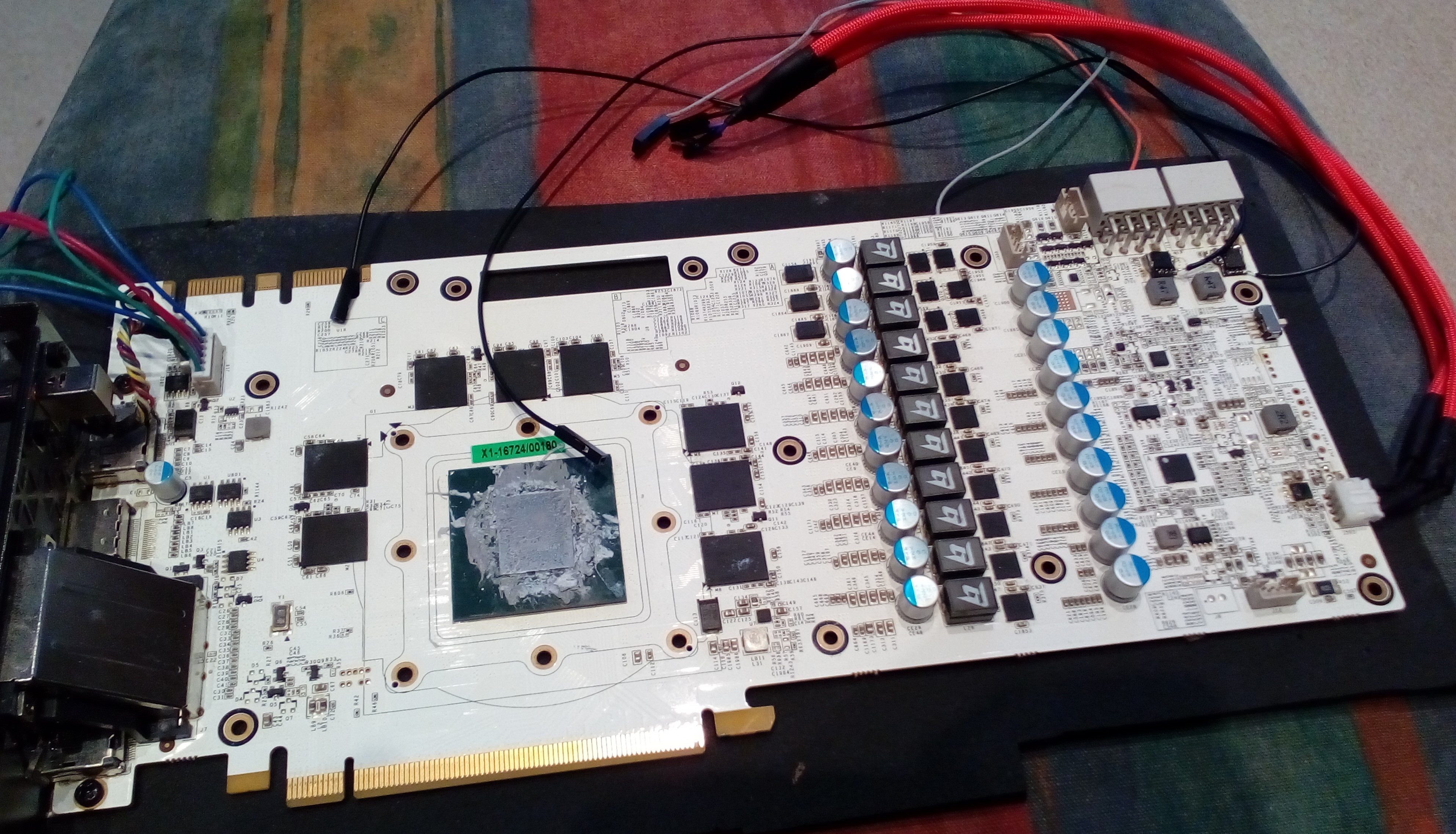
As test Subject I choose a GTX 1070 Hall of Fame, because it has easily accessible solder points for the I2C-Bus the INA3221 is on. I used a logic-analyzer to log all communication on that BUS passively, thus ensuring I do not interfere with the normal operation while getting the exact same information the GPU gets and uses for its power limiting algorithm.
This gives me shunt voltage and bus voltage at 100ms intervals. Since the bus voltage did not change by any meaningful amount, I ignored it.
As workload I ran GPUPI 3.2 2B at fixed clocks and voltages. I run that with no Resistor attached, 4k, 8k, 12k, and 16k, recording the shunt voltages for each run.
I then standardized it so that each run had the same number of samples in it and created a Graph showing the shunt voltage over time.
That looks pretty good already, as you can see the shunt voltage and therefor the reported power usage decreases consistently with lower VR settings.
Now let us try to validate Elmors chart.
The first step was to calculate an average for each run. The Value does not matter here, what matters is their relation to each other.
For example, the run without a Resistor was 0.898 that of the stock run, since the shunts are 5mΩ the effective resistance for that run was 5mΩ * 0.898 = 4.49mΩ. This is just the drop caused by the solder that is now on the shunt, the MOSFET should not come into play yet.
For the following calculations this will be the new “shunt resistance” and the MOSFET will be a resistance in parallel with it, forming the total resistance.
Using the same principle as above to calculate the effective resistance and then formula for 2 parallel resistances we can now calculate the MOSFET resistance for each run.
Example for 16k:
No VR / 16k = 0.741
4.49mΩ * 0.741= 3.327mΩ
So, 3.327mΩ was the effective resistance with 16k set on the VR.
3.327mΩ = (Rmos * 4.49mΩ) / (Rmos + 4.49mΩ)
<=>
3.327mΩ * Rmos + 14.938mΩ = Rmos * 4.49mΩ
<=>
14.938mΩ = 1.163 * Rmos
<=>
Rmos = 12.844mΩ
Doing the same for all other settings we get this table (small difference due to rounding):
And Putting these values into the reference chart:
The values are much closer than I was personally expecting. Especially in the typically used range of 5mΩ or less they are essentially dead on.
I am really satisfied with the Results of this testing as well as the PLM itself, I ran this card under Liquid Nitrogen and it work as expected.

I was recently a long time ago asked to share some details about my testing with the Elmorlabs Power Limit Modifier.
So that this does not become too long I will assume you are familiar with normal shunt Modding Techniques. The difference with these is that they do not have a fixed resistance but can be tuned without soldering again, even while the GPU is running. Pretty exciting, right? I wanted to test how well that works.
Elmor provided this chart as a reference.

As test Subject I choose a GTX 1070 Hall of Fame, because it has easily accessible solder points for the I2C-Bus the INA3221 is on. I used a logic-analyzer to log all communication on that BUS passively, thus ensuring I do not interfere with the normal operation while getting the exact same information the GPU gets and uses for its power limiting algorithm.
This gives me shunt voltage and bus voltage at 100ms intervals. Since the bus voltage did not change by any meaningful amount, I ignored it.
As workload I ran GPUPI 3.2 2B at fixed clocks and voltages. I run that with no Resistor attached, 4k, 8k, 12k, and 16k, recording the shunt voltages for each run.
I then standardized it so that each run had the same number of samples in it and created a Graph showing the shunt voltage over time.
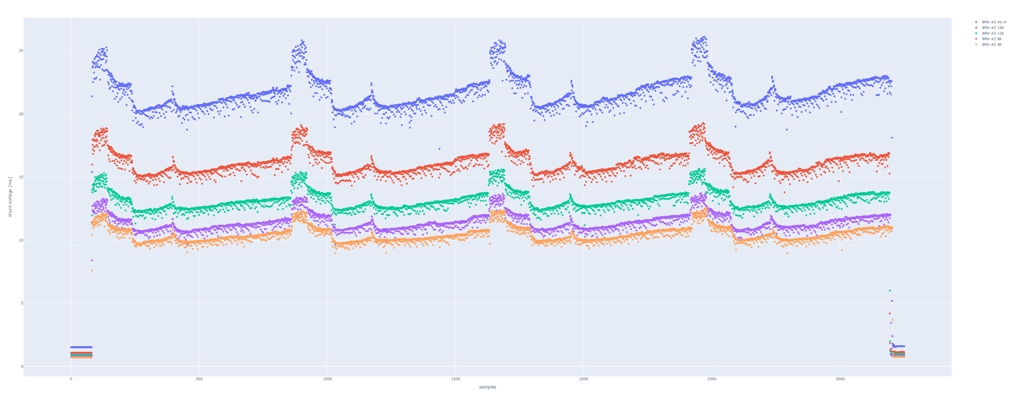
That looks pretty good already, as you can see the shunt voltage and therefor the reported power usage decreases consistently with lower VR settings.
Now let us try to validate Elmors chart.
The first step was to calculate an average for each run. The Value does not matter here, what matters is their relation to each other.
For example, the run without a Resistor was 0.898 that of the stock run, since the shunts are 5mΩ the effective resistance for that run was 5mΩ * 0.898 = 4.49mΩ. This is just the drop caused by the solder that is now on the shunt, the MOSFET should not come into play yet.
For the following calculations this will be the new “shunt resistance” and the MOSFET will be a resistance in parallel with it, forming the total resistance.
Using the same principle as above to calculate the effective resistance and then formula for 2 parallel resistances we can now calculate the MOSFET resistance for each run.
Example for 16k:
No VR / 16k = 0.741
4.49mΩ * 0.741= 3.327mΩ
So, 3.327mΩ was the effective resistance with 16k set on the VR.
3.327mΩ = (Rmos * 4.49mΩ) / (Rmos + 4.49mΩ)
<=>
3.327mΩ * Rmos + 14.938mΩ = Rmos * 4.49mΩ
<=>
14.938mΩ = 1.163 * Rmos
<=>
Rmos = 12.844mΩ
Doing the same for all other settings we get this table (small difference due to rounding):
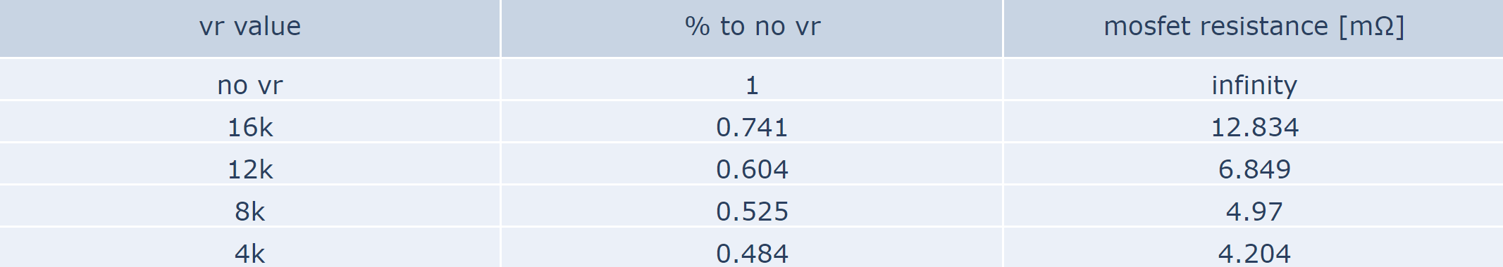
And Putting these values into the reference chart:
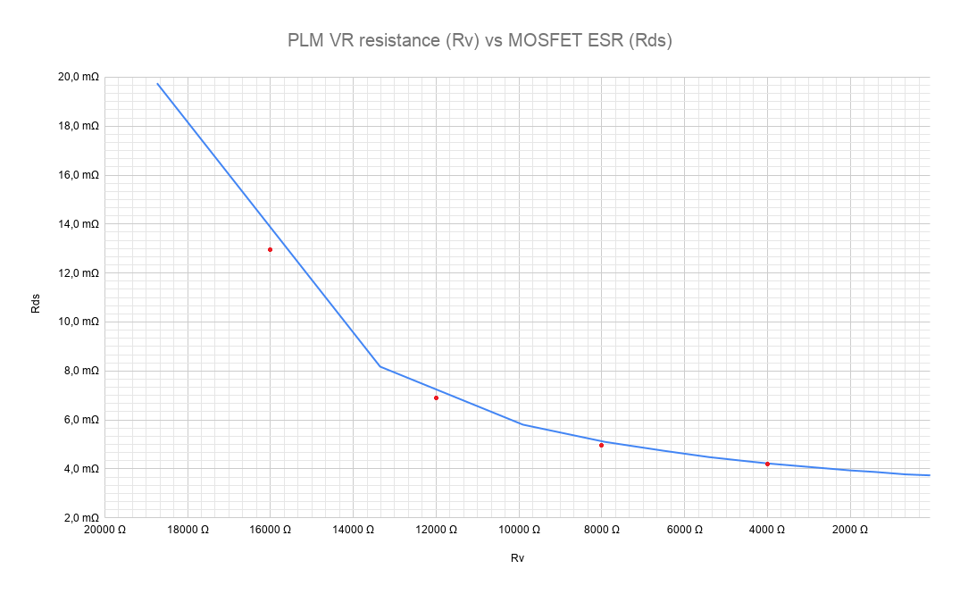
The values are much closer than I was personally expecting. Especially in the typically used range of 5mΩ or less they are essentially dead on.
I am really satisfied with the Results of this testing as well as the PLM itself, I ran this card under Liquid Nitrogen and it work as expected.
Uploaded files: